
UCLA Rocket Project
Prometheus: Recovery Systems Engineer
System Overview

Recovery Electronics and Parachute Buy
The Prometheus team at UCLA Rocket Project builds a hybrid sounding rocket every year and launches for competition before every summer. For the 2022-23 year, I was a Recovery Systems Engineer for the project, where I was responsible for designing and testing hardware used for recovering the rocket via parachute. The goal of our team is to safely bring the rocket back to ground after it has reached its maximum altitude.
General design of the recovery system
After the rocket has reached its apogee, the nosecone of the rocket is separated, deploying a drogue parachute. With a shock cord attached between the nose cone and the rest of the rocket, the drogue chute will decelerate the rocket enough for the main chute to safely deploy at approximately 1500ft.
Detailed Deployment Sequence
This years rocket “Casanova” was custom built and designed hybrid rocket powered by a solid fuel grain made from an ABS and liquid oxygen. Our goal was to reach over 10,000ft.
Once the rocket reaches apogee, this is when the recovery sequence begins, and separation occurs to release the parachutes. The recovery controller detects the velocity change approaching zero and the reducing atmospheric pressure to then trigger the release of compressed CO2 gas inside the recovery bay. The pressure inside pushes each end of the bay apart, shearing the nylon pins holding each end together, separating the recovery bay.
Both ends of the carbon fiber body tubes are held together by a long shock cord between their bulkheads with the drogue chute and main parachute attached in between. The drogue chute is deployed immediately after separation, this stabilizes and decelerates the rocket's descent to about 87 ft/s.
The main chute remains packaged until about 1500 ft where the recovery controller detects this altitude and triggers a chord cutter to release the main parachute. Once fully deployed, the entire rocket should descend to approximately 26 ft/s.


Equipment and Technical Specs
Shock cord:
Size - 1in width
Expected shock force: ~1000lbs
Max shock force: 4000lbs
Recovery Controller:
RRC3 – Rocket Recovery Controller 3
Implement two independent circuits for redundancy
Powered by 9V batteries
Pull pin start
Drogue chute:
24" FRUITY CHUTES: DROGUE CHUTE
Size - 24in diameter
Released at apogee
Coefficient of drag - 1.5 to 1.6
Slows rocket to ~87 ft/s
Shape - Elliptical
Main chute:
84” Rocketman Elliptical Parachute
Size - 84in diameter
Released at ~1500 ft
Coefficient of drag - 2.2
Slows rockets to ~26 ft/s
Shape - Toroidal
Design
Past design
The recovery bulkhead for the previous year was made of wood and epoxied directly inside the body tube. That design was reliable and airtight, but rather difficult to assemble. It used a Peregrine CO2 ejection system permanently mounted to the bulkhead. CO2 canisters had to be screwed in at an arm's length away inside the body tube, which was rather difficult. However the most critical issue was wiring the e-matches at length and then pushing the recovery electronics mount into the tube and hope the wires remain connected properly.
Improvements
For this year, we worked with internal structures to design a removable bulkhead machined from aluminum, where our recovery system can be assembled outside the body tube and then mounted in place.
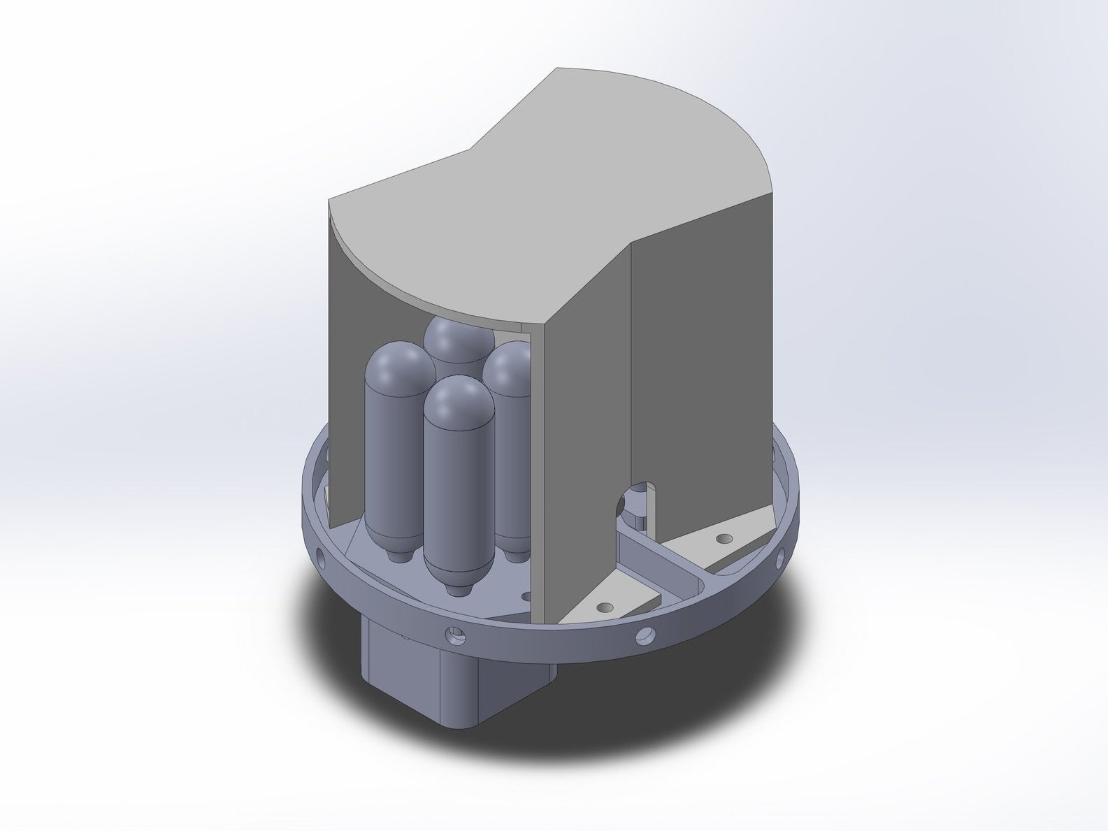
The next major change was the CO2 ejection system itself. Past experiments have shown that a minimum of 4 12g CO2 is needed to reliably separate with 4 shear pins. The Peregrine CO2 ejection system only punctured one canister per e-match charge. In order to reduce the number of failure points, we wanted to design something that would puncture multiple canisters with a single charge. Also, the needs of the payload team were in limbo, and the size of the parachute was up in the air for a long period of time. To accommodate this, we wanted the system to be flexible, with the ability to scale up the number of canisters to 8 in total.
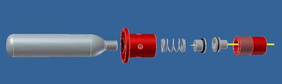
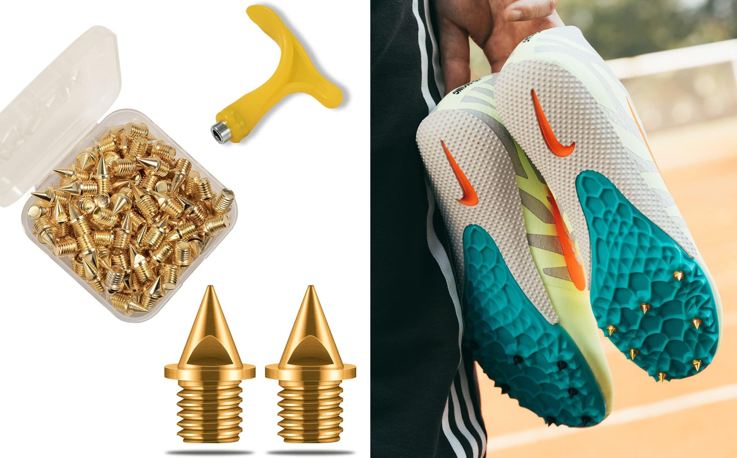
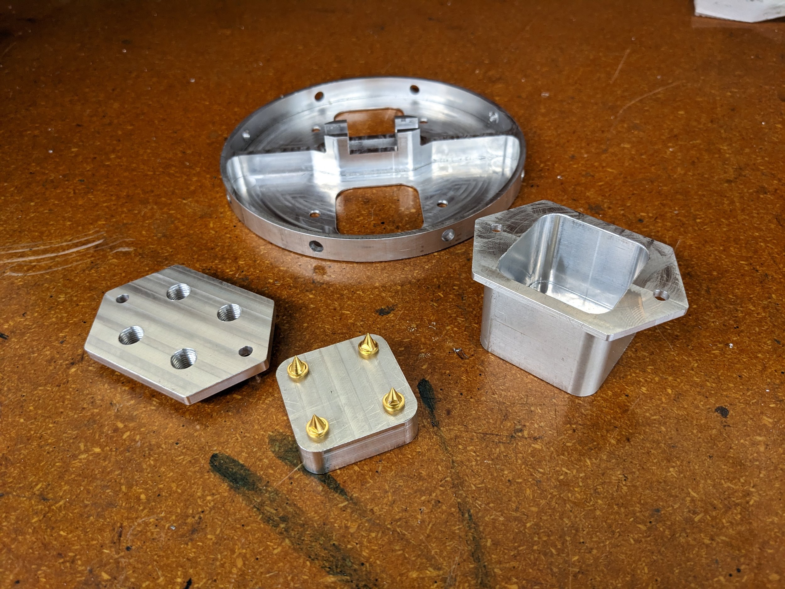
The design we went with had a piston in a squircle shaped combustion chamber, where an e-match would detonate a small amount of black powder and push a plate with 4 spikes into 4 canisters, puncturing them. For the spikes, we wanted something replaceable and readily available, and threaded track shoe spikes were perfect.


CAD
Below is the final CAD with the puncture system, bulkhead, and electronics mount.


CO2 Puncture Mechanism
Manufacturing
3D Printing and Electronics
Before CNCing anything we wanted to make sure the dimensions all felt right, particularly between the inner walls of the combustion chamber and the outer walls of the puncture plate.
We also needed to test fitting the electronics together with the pull-pin mechanism. To save battery life, the recovery system is initially deactivated with a pull pin obstructing the circuit to the power supply. Once fully integrated on the pad and ready for launch, the pull pin is removed (accessible from the outside) to activate the electronics, and a sequence of beeps is heard if armed. Testing the triggers for altitude changes was done inside of a pressure chamber.


CNC Machine
This year's Rocket Project was lucky enough to have an experienced machinist on the team, Cameron Zamora. He helped me with the CAM programming (HSMworks) in SolidWorks and ran the CNC machine (Haas) for the recovery parts and all the rest of the parts for this years rocket.


Testing
Puncture chamber
Our first test successfully proved the canisters would be punctured, but it also showed that gaskets were needed to prevent gas from flowing back into the electronics bay. We used 0.5g of black powder per chamber for this test, which was a rough estimate (guess) that happened to work out, and we stuck with this amount from here on out.


Separation
With the next series of tests the focus was on separation and sealing. We ended up not needing the larger chute, as the payload needs were greatly reduced. We began testing with 6 canisters, leaving 2 spent canisters on the mount. We were getting consistent separation but with significant blow back into the electronics bay. Gaskets were in place and working well, however the blow back was coming through the outer edge of the bulkhead.


Separation Test
Separation with deployment and electronics
For the final separation test, we packed the body tube with a dummy chute and sealed the bulkhead with gaff tape. It’s not the most elegant solution but the best we could do in the time frame. Separation worked perfectly and the electronics remained safe and sound.


Parachute packing and testing
Packing the parachutes is a tricky and delicate matter, but after a few tries we got the hang of it. The most difficult part is keeping the lines/gores from tangling while packing. For the drogue, it ended up being best to just roll the whole thing up like a sleeping bag. For the main, it was best to fold it up like an umbrella first, then push it straight into the bag with lines carefully winded through the outside loops.
To test, we threw the drogue off one of the bridges on campus and dragged the main behind an accelerating car. Both tests showed that our packing methods would not tangle on deployment.


Montage of recovery testing
We had a ton of fun performing these tests, videos of most of them are below!
Integration
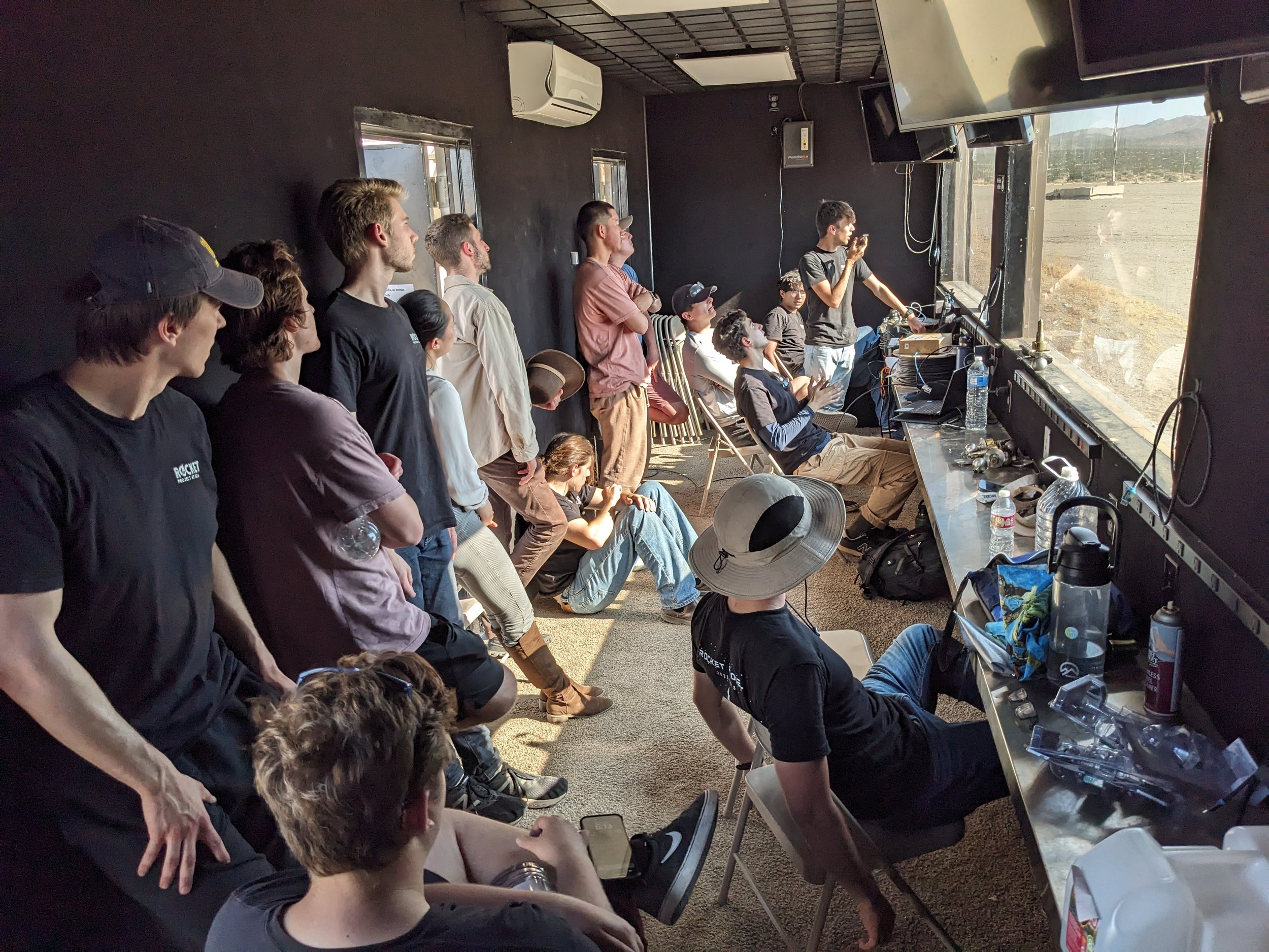
Final integration was done at the launch site in Mojave. A number of small issues came up at the last minute, mainly with cable management of the electronics. After soldering everything together, the cables were difficult to manage while integrating. We ended up just kind of wrapping everything in duct tape to keep it together. Not ideal, but the safest thing we could do in the time period. Still, it was a lot fun that day, and it was great working with everyone!


Launch
Unfortunately our system never got a chance to fly… A little backstory, the rocket is connected to various ground system controls: Quick disconnect for fueling and pressurization, electronics for sensors, and several pneumatic hoses for valve control. For safety, if the electronics are disconnected, the rocket enters a safe mode that closes all the valves and depressurizes the tanks.
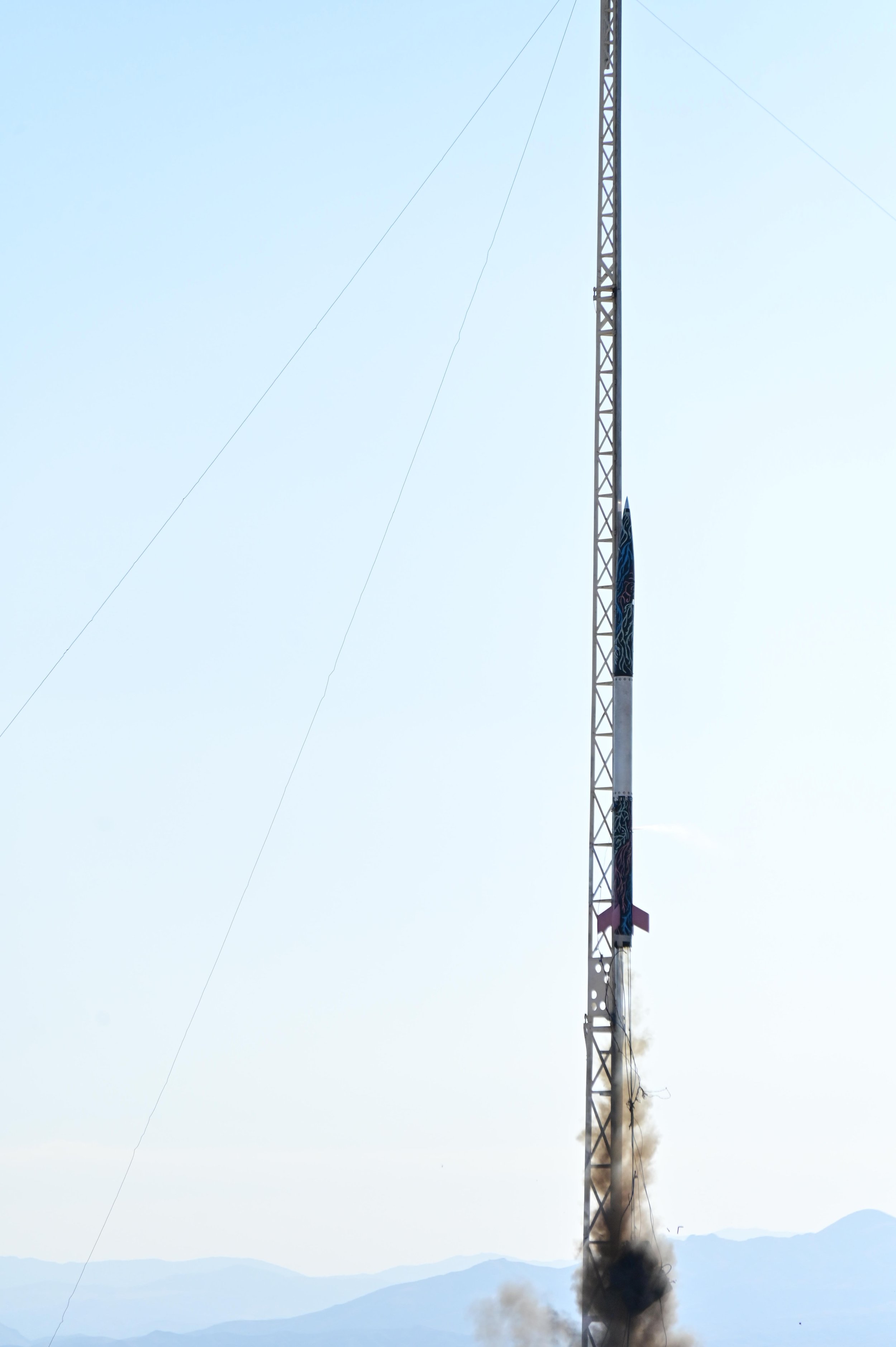
When we launched, the electronics disconnected, as it should, but the pneumatic systems remained attached slightly longer than expected. This gave the safe mode command a chance to run. With the pneumatics still attached, all the valves closed barely a second after the engine started. Then, because the rocket was only partially up the rail, it slid back down, slamming into the base.


Reflection
While I think our system was a vast improvement of past systems, it wasn’t without its troubles.
First place I would look for refinement is the integration of electronics on the mount. As time ran out, we opted for velcro tape and duct tape for the final assembly to keep cables from tangling. This is a rather in-elligent approach that could use iteration on.
Next is the bulkhead seal to the body tube, where again we went with a tape, which isn’t the best idea and was also difficult to adhere inside the tube. A better approach may be to have a rubber skirt on the outer edges of the bulkhead.
Also, a spring should have been implemented as a safety measure inside the chamber. In retrospect, it was rather risky relying on the friction fit to prevent a premature puncture of the CO2 canisters.
Overall I think the ejection system itself is rock-solid, but the design with the rest of components need some refinement.
This has been a great experience and I had just so much fun. I will be a Recovery Lead on the 2023-24 Ares rocket and I can’t wait to get to work!