
DIY Star Tracker
For long exposure astrophotography
When photographing the cosmos, gathering as much light as possible is critical to producing a decent image. The most practical way to achieve this is with a very long exposure time. Unfortunately for us terrestrial beings, our planet is spinning, streaking these exposures. This can be counteracted by panning the camera precisely with the rotation of the Earth, tracking the stars. And that is what I’ve built here, a Star Tracker.
Requirements:
Support 6-7 lbs of camera equipment
Portable power supply
Run for 2hrs+
Design
Structure
The simplest most cost effective design is a “Barn Door” tracker. A camera is mounted on a “door”, with the hinge aligned with the axis of the Earth. This is then slowly opened at the same speed of the rotation of the Earth, raised by a threaded rod that is driven by a motor.
For this design, if you imagine the threaded rod being a full circle, it should take 1 day (1436 minutes) for the motor to make a complete loop. The rate we need to travel is then given by:

However since we are traveling along a threaded rod, the rate is given by the rotations per min (RPM) divided by the number of threads per inch.
Putting these together, the basis for the design follows this function:

Supporting the weight of the camera influenced every aspect of this build. The camera and lens total about 7 lbs, and because of the peculiar angles needed to align the mount and frame a shot, the center of mass can deviate far from the center of the tripod.
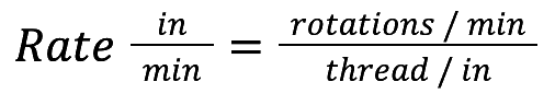
I went with hardwood ½” oak boards for my base. Being wood, this allowed for easy customization and would help absorb minute vibrations from the motor. To ensure it could handle the weight, everything would have to be bolted, screws directly into the wood could work their way loose too easily.
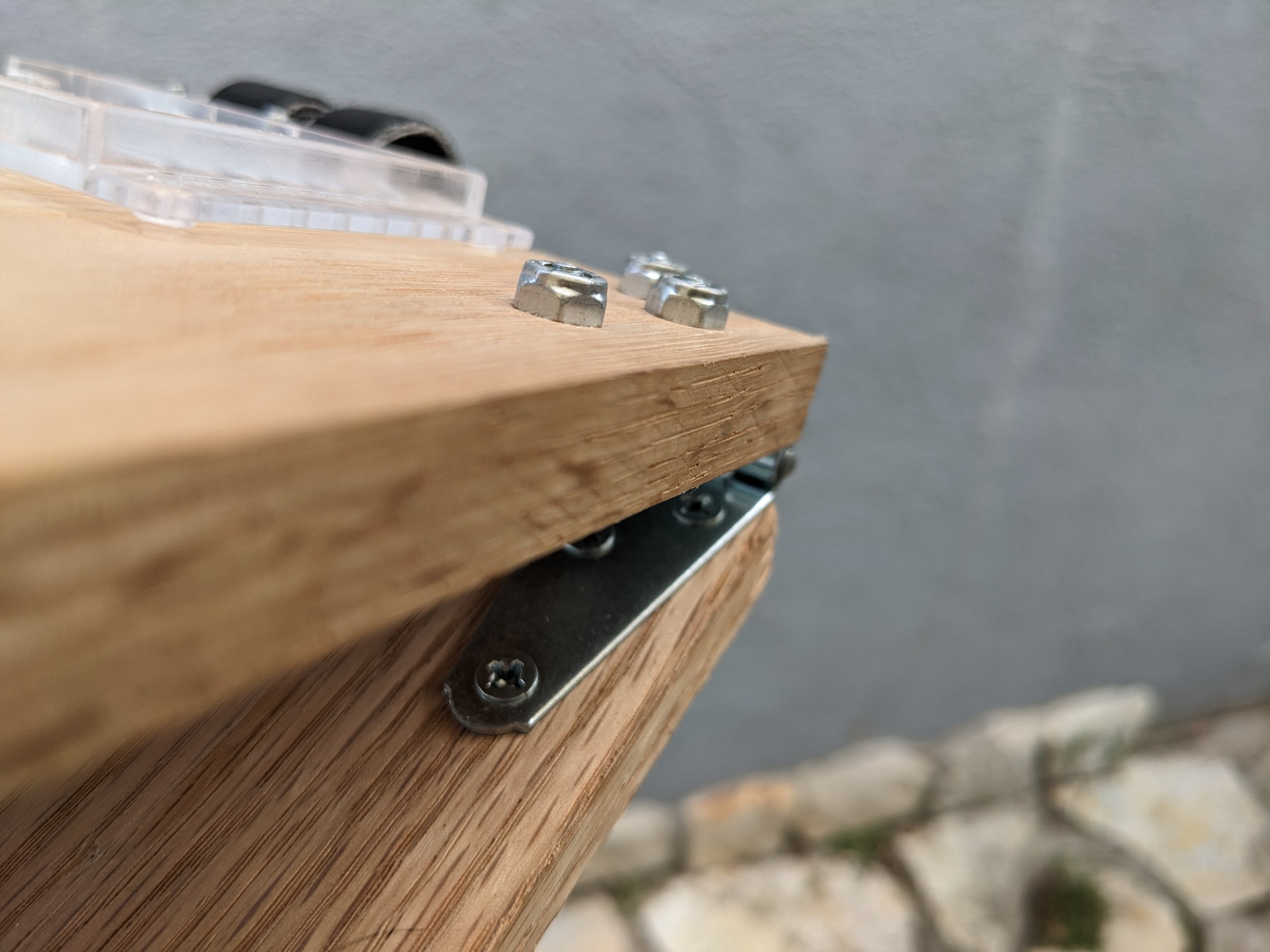
The foundation of this setup needed to be threaded into a standard tripod plate. This would allow for most flexibility when leveling and aligning with Earth's axis. A bolted pronged T nut proved to be the most sturdy, I also added several layers of gaff tape around the base for extra friction. (Although a better design may be small sheets of dense rubber) For the top tripod mount, it needed to be extended above the board to allow more range of motion when framing a shot. This was bolted all the way through directly to the tripod head, with a rubber gasket for added friction.


Materials:
Structure:
24x5½”, ½” thick Oak board
Hinge (x2)
Bolts (x6)
Locking nuts (x6)Base Connection to Tripod:
Pronged T nut (same thread as tripod base plate)
Bolt
Washer
Locking washerTop Tripod Connection:
Manfrotto 3-Way Head with Foldable Handles (MH293D3-Q2)
https://www.amazon.com/gp/product/B00B981E3E/
2” Oak cube block
Bolt (same thread as tripod head)
Washer
Locking washer
Rubber Gasket
Motor, Threaded Rod, and Gears
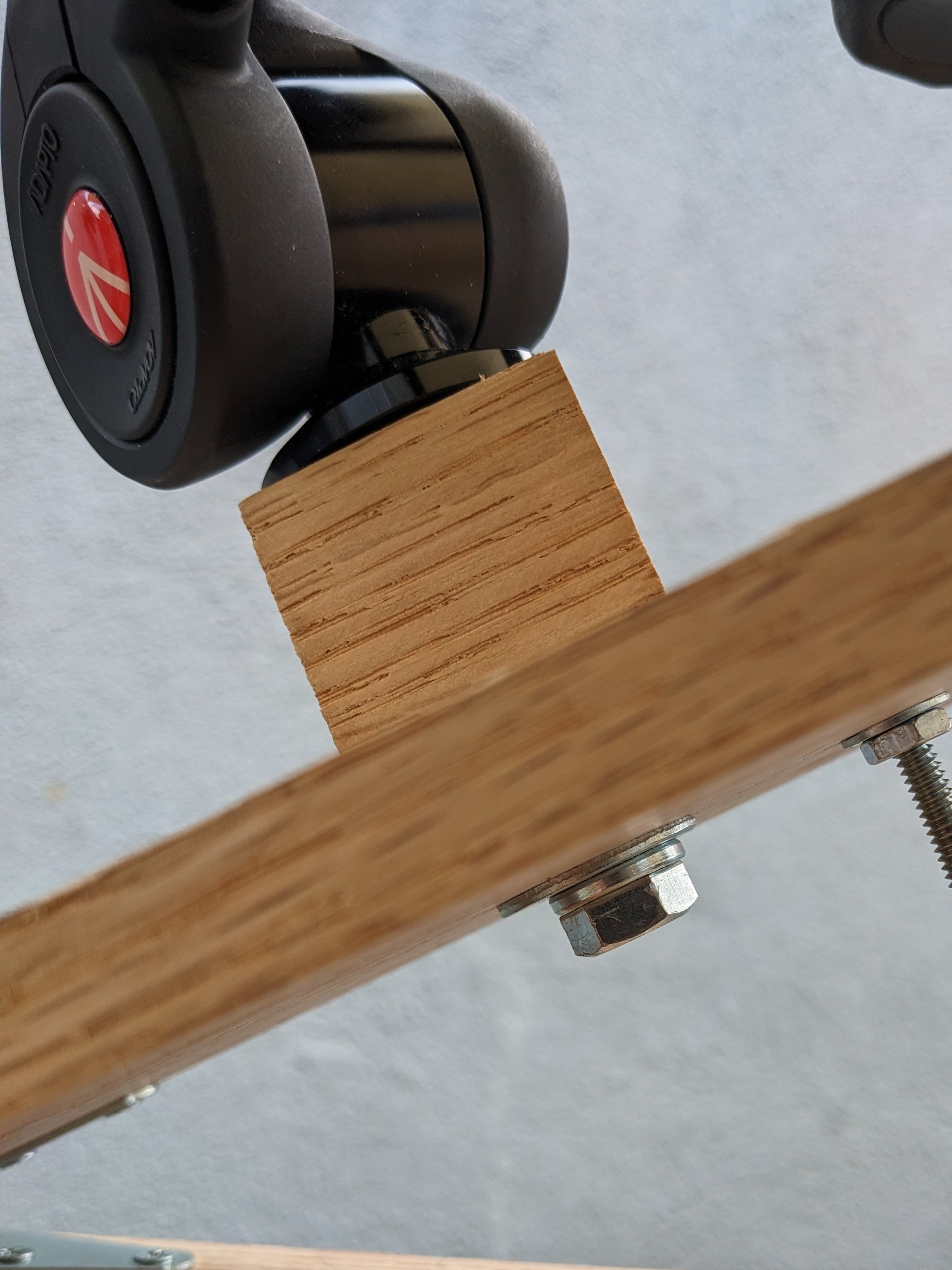
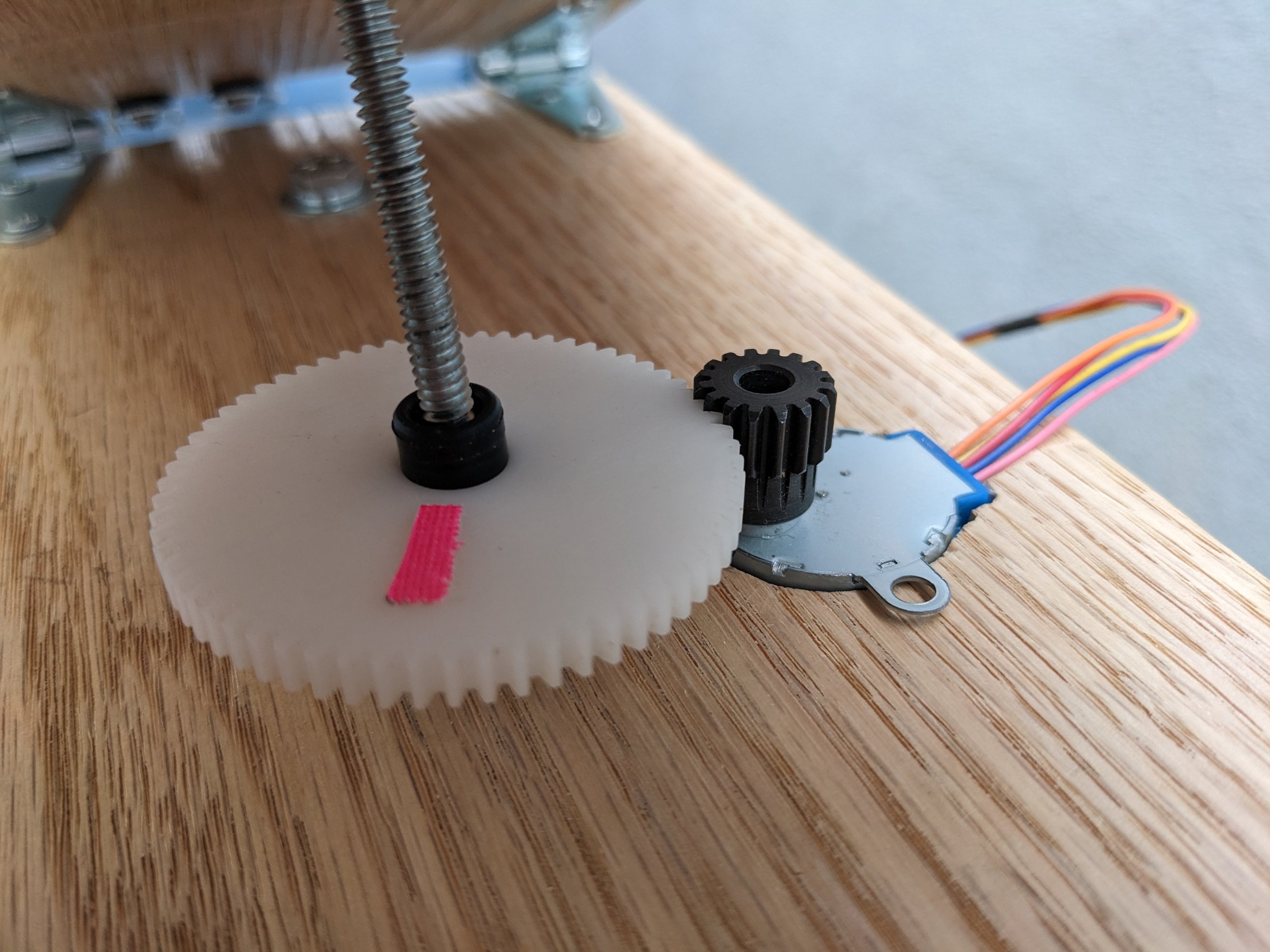
A tricky but critical part of this build is that the rod gear itself needs threads. The easiest way I figured out how to do this is with a well nut, which is like a rubber plug with a threaded nut in it and is found at most hardware stores. I just had to be very careful about finding the exact gear with a bore size to fit this snuggly (link below).
To power the slow opening of the hinge, I’m using a motor to drive the threaded gear along a curved threaded rod. I chose the 28BYJ-48 Stepper Motor for it’s compact size, low speeds, and high torque. Perfect for this project. It has two modes, “Fullstep” and “Halfstep”, half step has double the number of steps per rotation, making it more precise. The torque is listed as 0.5190 pound-force inch in this Halfstep mode.
That motor will be driving a 16 tooth gear with a 64 tooth gear threaded on the rod, a 4:1 gear ratio.


Gear Ratio Equation:


Screw Equation:

Friction (θs):
Since I’m lubricating the thread and well nut with WD-40, this should eliminate most of the friction, I’ll assume Friction(θs) ≈ 0.
Thread Angle (𝛂):


The motor is capable of applying enough torque to lift almost 40 lbs just on its own. With a gear ratio of 4:1, this is multiplied by 4, so it could theoretically lift 160lbs! Not bad for a little $5 motor, and well beyond what this project requires.
I decided to have a 7 inch radius hinge, which means the arc radius of the threaded would need to be 7 inches. To do this, I created a 14 inch diameter circle in Photoshop, printed it out, and bent the rod over my knee until it lined up with it. The length of the rod will determine the amount of capture time that can be achieved. To fit on my tripod, the maximum I could fit was about 8 inches, which comes to about 4 hours of capture time.

Materials and Info:
Threaded Rod:
12” 10-24 Threaded Rod
https://www.machiningdoctor.com/threadinfo/?tid=18Motor:
28BYJ-48 Stepper Motor with ULN2003 Driver
https://www.amazon.com/ELEGOO-28BYJ-48-ULN2003-Stepper-Arduino/dp/B01CP18J4A/
https://www.makerguides.com/28byj-48-stepper-motor-arduino-tutorial/
https://www.solarbotics.com/product/22310/
Fullstep mode: 821 gram-force centimeter = 0.7126 pound-force inch
Halfstep mode: 598 gram-force centimeter = 0.5190 pound-force inch (more precise)
https://www.airspayce.com/mikem/arduino/AccelStepper/classAccelStepper.htmlGear Info:
32 Pitch 16T 5mm Hole Pinion Gear
https://www.amazon.com/gp/product/B09BMD4V1J/
32 DP, 64 Teeth, AGMA 10, Acetal Gear, Hubless: S1288Z-032D064
https://shop.sdp-si.com/catalog/product/?id=S1288Z-032D064
Computer and Software
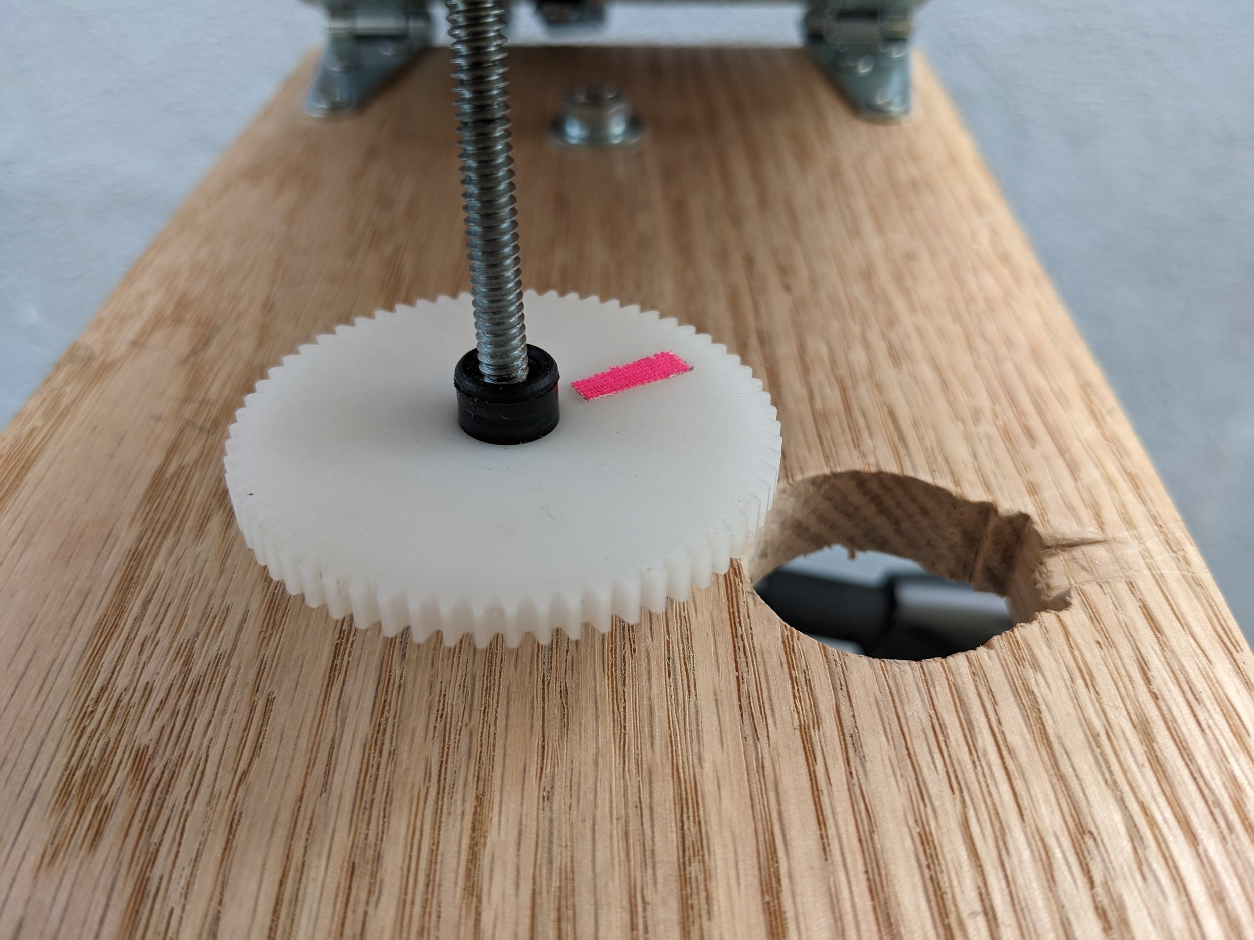
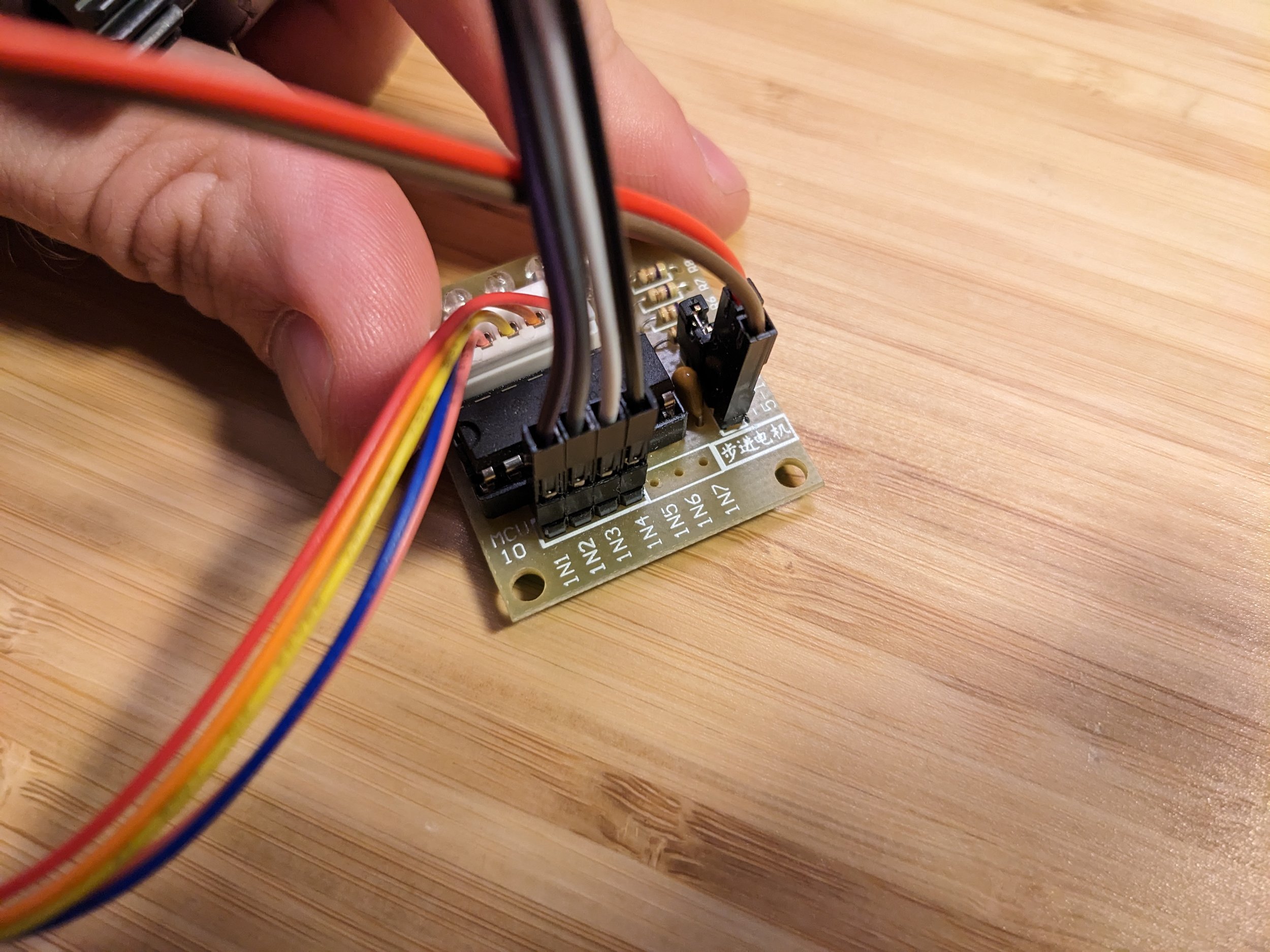
I’m using an Arduino Uno 3, LCD Keypad Shield, with a Rechargeable Battery Shield sandwiched in between. This combination of electronics together came out rather bulky, but still very convenient. The LCD shield has programmable buttons that I used for starting and stopping the motor as well as adjusting the speed. This build needed to be mobile, so the battery shield was vital, it also provided the unit with an on/off switch.
The wiring varies slightly depending on the exact component you buy, and can be a bit confusing to figure out, hopefully the photos below tell the story.


From the Barn Door equation, this calculates the needed RPM for the threaded gear:

Again, with a gear ratio of 4:1, the needed RPM of the motor:

The motor is programmed by steps per second, steps referring to the gears in the motor itself. In Halfstep mode, (which is more precise) 1 rotation = 4076 steps. This comes to:

For the Arduino, LCD Display, and stepper motor, my code is posted below. The LCD display provides feedback on the status of the motor (Running or stopped) and the current speed of the motor, with key presses that can adjust the speed. This is in case the actual speed needed differs from the calculated speed. (But also I have some creative ideas that I was curious to experiment with in the future as well ;) )
Arduino Code: https://github.com/blind-quist/DIY-Star-Tracker/blob/main/StarTrackBL.ino
Materials and Info:
Arduino Uno:
https://www.amazon.com/gp/product/B008GRTSV6/LCD Shield Info:
DFROBOT Gravity 1602 LCD Keypad Shield
https://www.amazon.com/gp/product/B006D903KE/
https://wiki.dfrobot.com/LCD_KeyPad_Shield_For_Arduino_SKU__DFR0009Battery Info:
energyShield 2 Basic - Rechargeable Battery Shield
https://www.amazon.com/gp/product/B06VVBRR7H/Cables:
Breadboard Jumper Wires
https://www.amazon.com/gp/product/B01EV70C78/
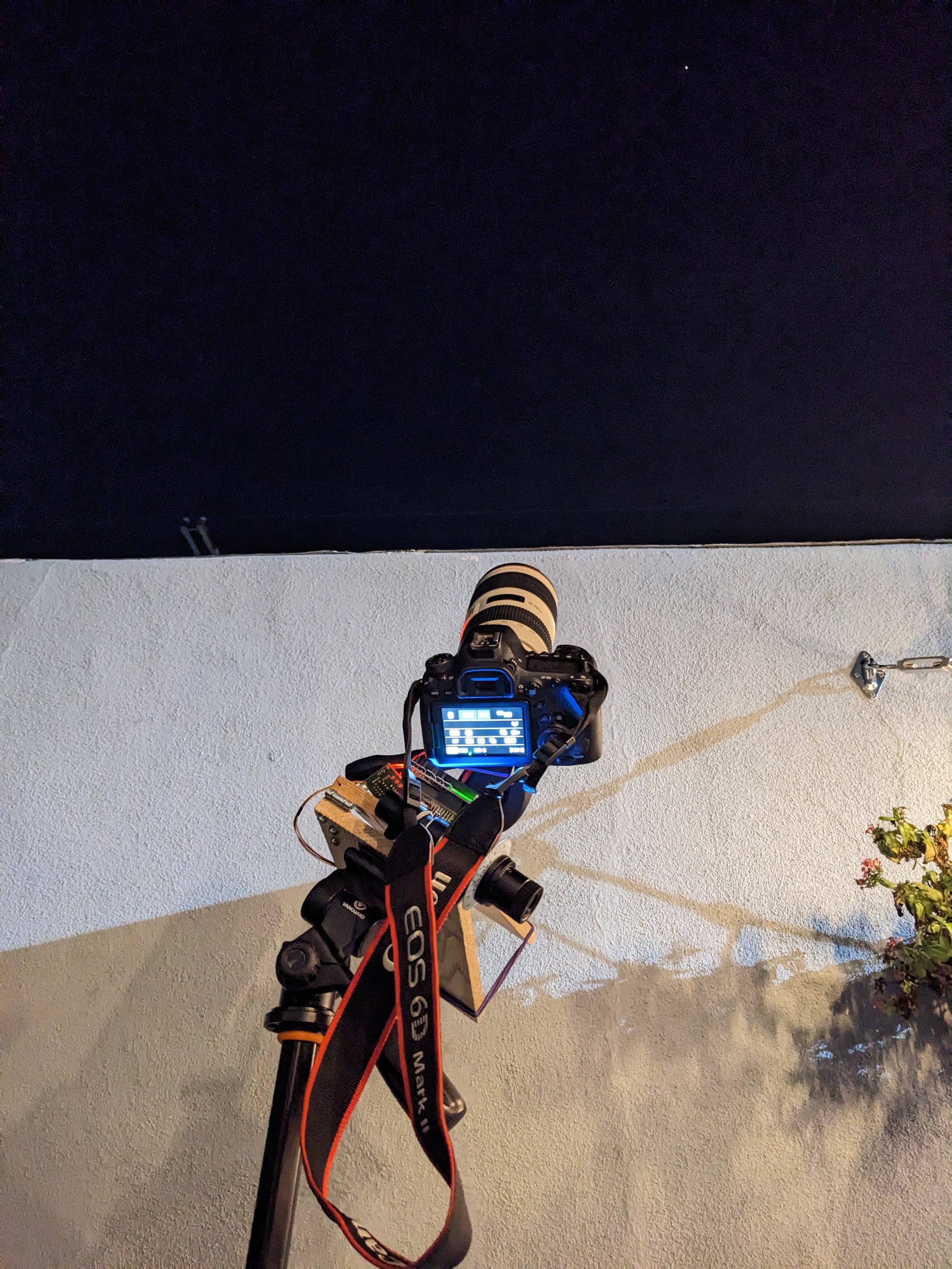
Polar Alignment
The last critical part for this setup is the Polar Alignment scope. I used pipe hangers to attach it as close as I could to the hinge. Proper alignment is vital to getting clean exposures and is an art form in itself. The quick tutorial: Point the axis of the hinge at the star, Polaris. (A night sky AR app is great for this, I used Google Sky.) Use a polar finding app to display the orientation of the constellations and where Polaris should land in the scope at your location, elevation, and time. Rotate the scope and adjust the tripod accordingly to line Polaris as close as possible.


Materials and Info:
Polar Alignment Apps:
PolarFinder Pro (Android): https://play.google.com/store/apps/details?id=com.lunari.polarfinderpro&hl=en_US&gl=US
Polar Scope Align (iOS): https://apps.apple.com/us/app/polar-scope-align/id970157965
(There are many others)Polar Alignment Scope:
Astromania Polar Alignment Scope for EQ-5
https://www.amazon.com/gp/product/B07M62XY9G/Tripod:
Vanguard Alta Pro 263AP Aluminum Tripod with PH-32 Panhead
https://www.amazon.com/gp/product/B00CCA1Y3S/
Results
My first tests had an issue with there being a subtle wobble showing up in the images long exposure. It’s a rather inelegant solution, but adding rubber bands over the hinge seemed to eliminate this. Then once I got the hang of aligning the polar scope without bumping the tripod, it seems to work! My calculated speed of 199.72 steps/sec even seems to be spot on.
These are from my first test. Not very glamorous, as they were shot from the middle of Los Angeles on a not particularly clear night, but to my excitement it shows it was working!


After a few difficult nights, I finally started to get the hang of it, and I got a decent photo of the Andromeda galaxy! It was pretty windy on the mountain I was on, so I was only able to get 10 photos suitable for stacking, but I’m still very pleased. The tracker is working great!
Reflection
I think the first place to look when improving this build is the threaded rod. I had trouble with small shaking occurring as the gear threaded through it. Adding the rubber bands did seem to solve it, but I’m not particularly fond of the solution. I think switching to a much thicker threaded rod would fix this, distributing the load more, and reduce the wobbling. Although it would be more difficult to bend the rod and finding a gear to thread through it would be trickier as well.
A work around may be to keep the threaded rod straight, and keep it held in place with a pin joint. Which is something this build has done: https://www.reddit.com/r/astrophotography/comments/1jk0h5/equipment_homebuilt_tracking_mount_up_and_running/
In the same vein, a well nut in a gear is not the greatest design. I am concerned this may cause issues during cold nights, as the rubber may not be able to maintain adequate friction in lower temperatures. I’m also suspicious that it is slipping every once in a while. A metal gear with welded nut may be a better solution, however getting the nut welded in the EXACT center may be challenging to do. This build was a major inspiration for mine, and he accomplishes this: https://www.instructables.com/Star-Tracker-Using-28BYJ-48-Stepper-Motor-and-LCD-/
Next pain point is the computer housing and cables. I would love to figure out a way to hide the cables more and create a housing for the Ardunio.
Overall I’m very pleased with this first iteration, but I can’t shake my desire to improve it!